Nearly 6 months later, and after back-burnering the project multiple times, I’ve made some significant progress on the LEDBrick aquarium light. In the space between blog posts, I’ve:
- Received a round of metal-core PCBs for the LEDs.
- Designed an 8 channel driver board based on the L3414, a different sketch from the original planning
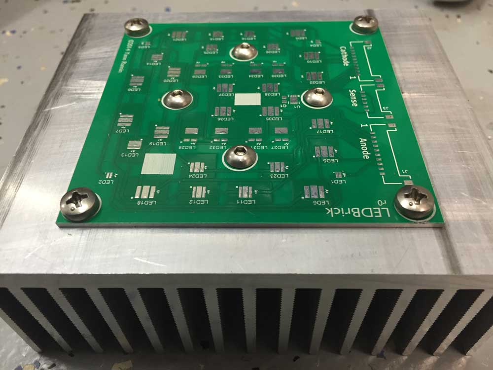
- Machined a single heat sink, and did test mounting of the emitter board.
- Populated one emitter board.
- Did thermal testing
- Built a single driver board and did a full integration test.
Incomplete GitHub sources
All of these designs are considered Open Source Hardware under the CERN license, and can be fetched from GitHub. The design files are likely incomplete, but will be updated as progress is made.
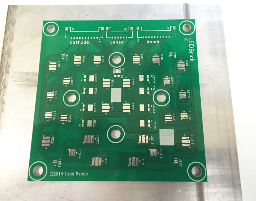
Emitter Board
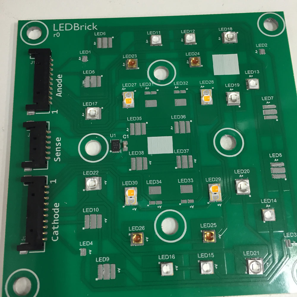
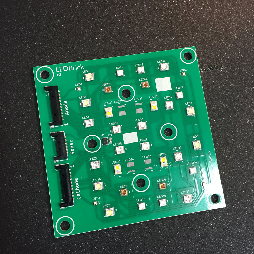
The emitter board, from Gold Phoenix PCB, arrived in good shape. Here are a few shots of the board sitting on top of the target heat sink.
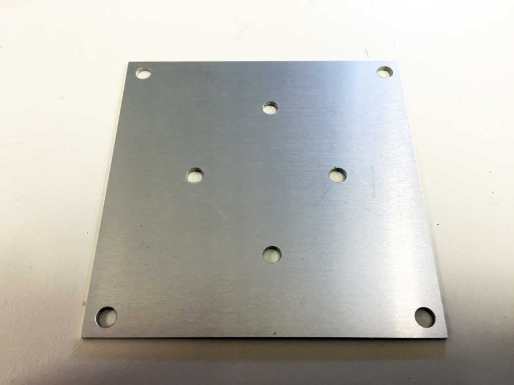
Drill and tap
Using metric M4 size screws, with a 3.2mm drill.
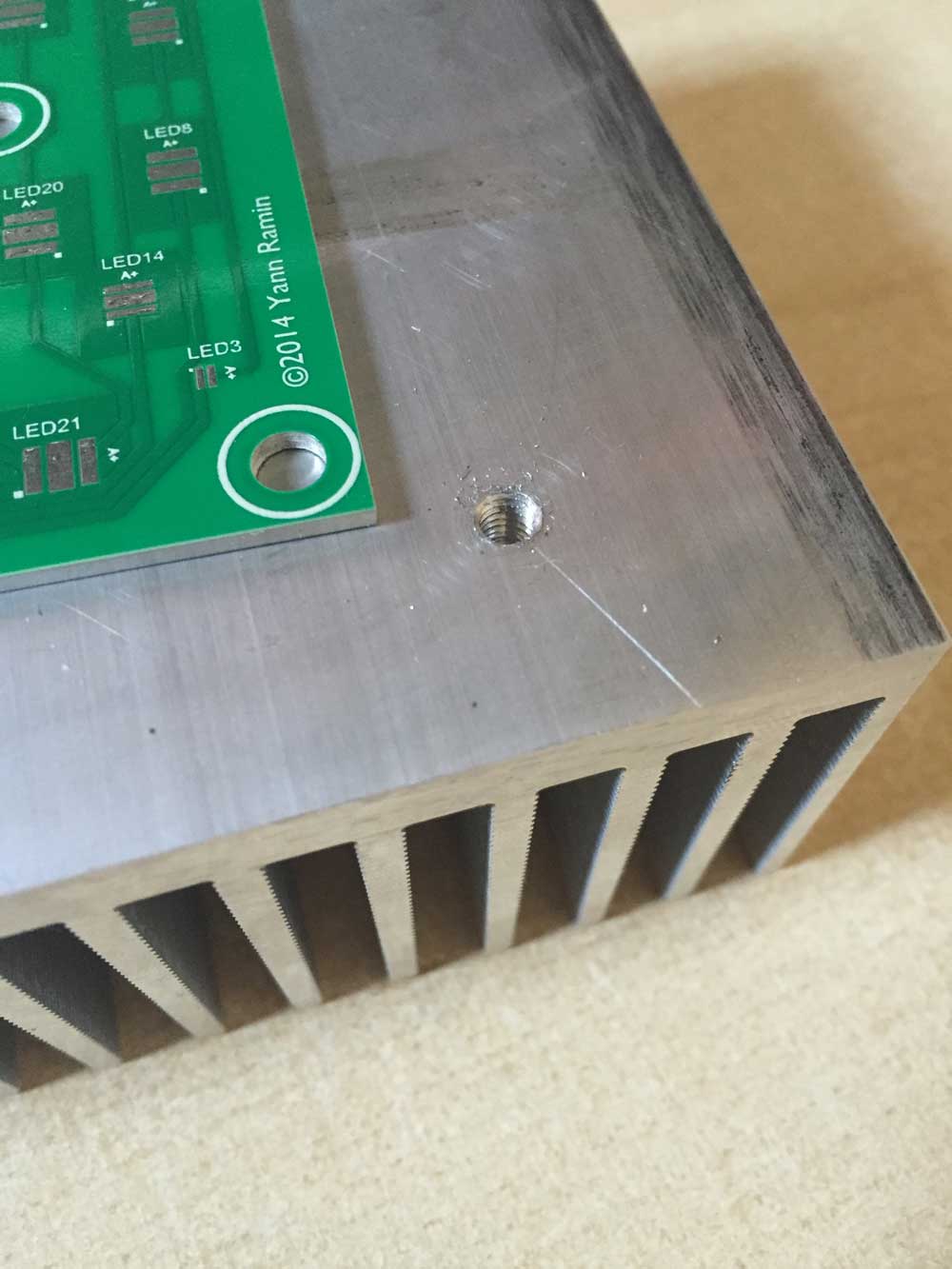
The four corners are targeted to have M4 threaded rods inserted through the heat sink with a captive nut on the bottom mount. This part isn’t shown here.
Building an emitter board
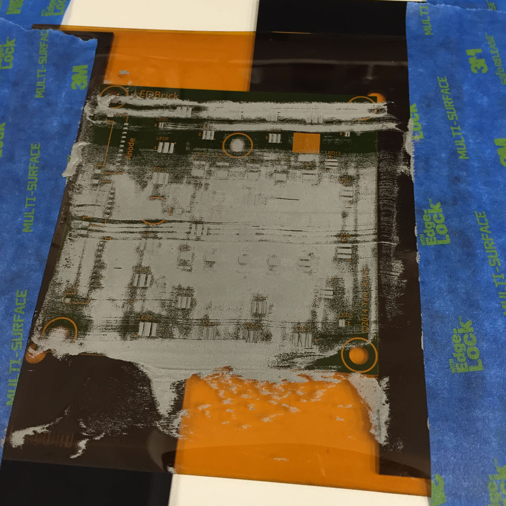
The emitter board was built via a stencil + paste and hot plate method. Hand-soldering onto a metal core PCB is an exercise in frustration - you need to apply heat to the core in order to make any progress. The stencil here is from OSHStencils
The first step is the paste:
Next up, place the parts:
Toss on a heating hot plate, and give some top side assistance from a hot air gun to make sure everything is flowing nicely:
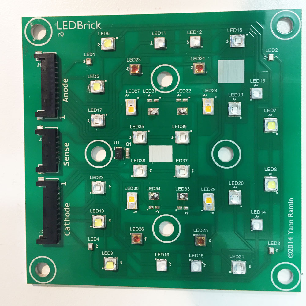
And the end result:
Testing the emitter
I started building the cable harness, which consists of Molex Pico-Lock 1.5mm blade style connectors. I used an Engineer PA-09 crimping tool, with a small post-crimp adjustment (basically, smash the connector to be a bit thinner on the secondary insulation crimp).
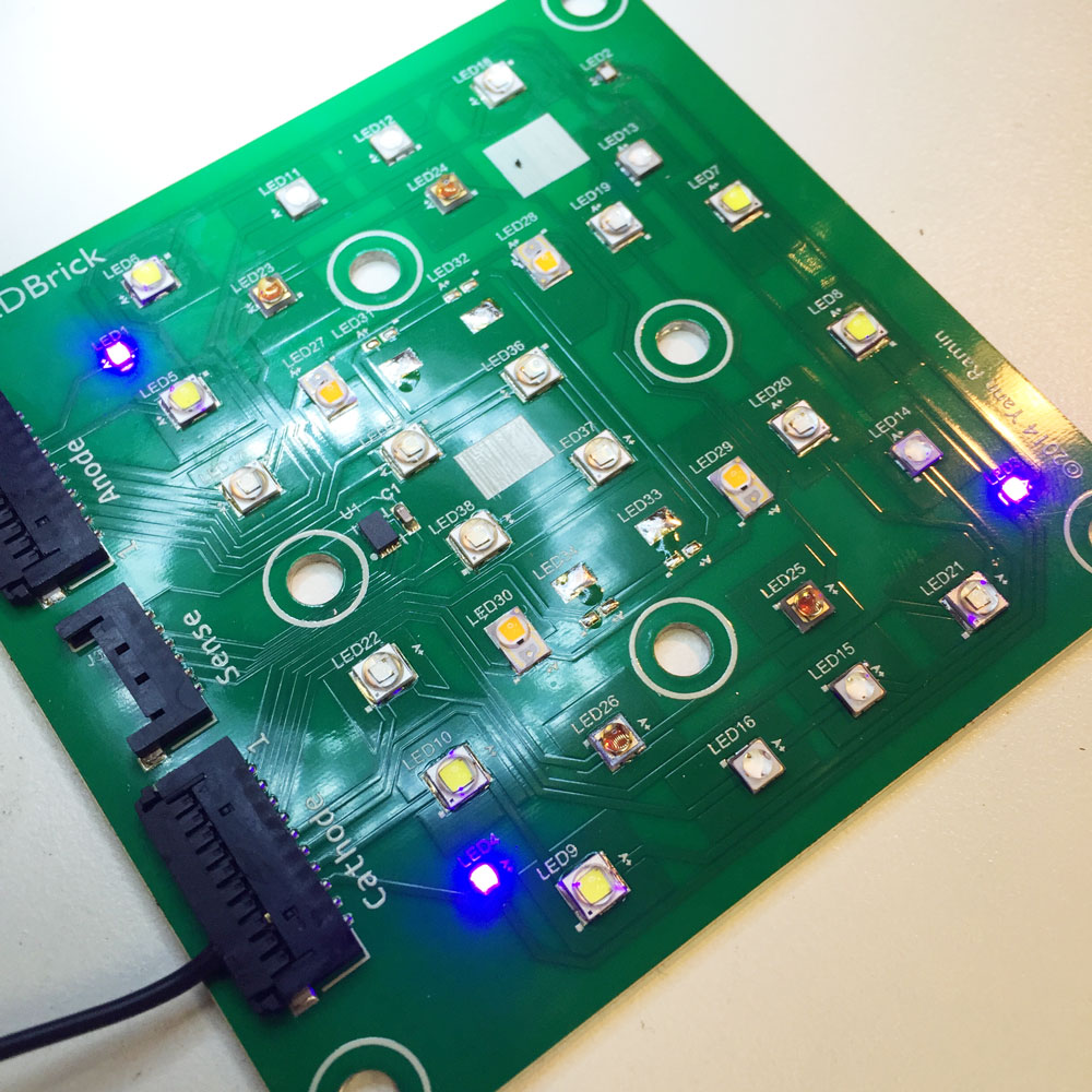
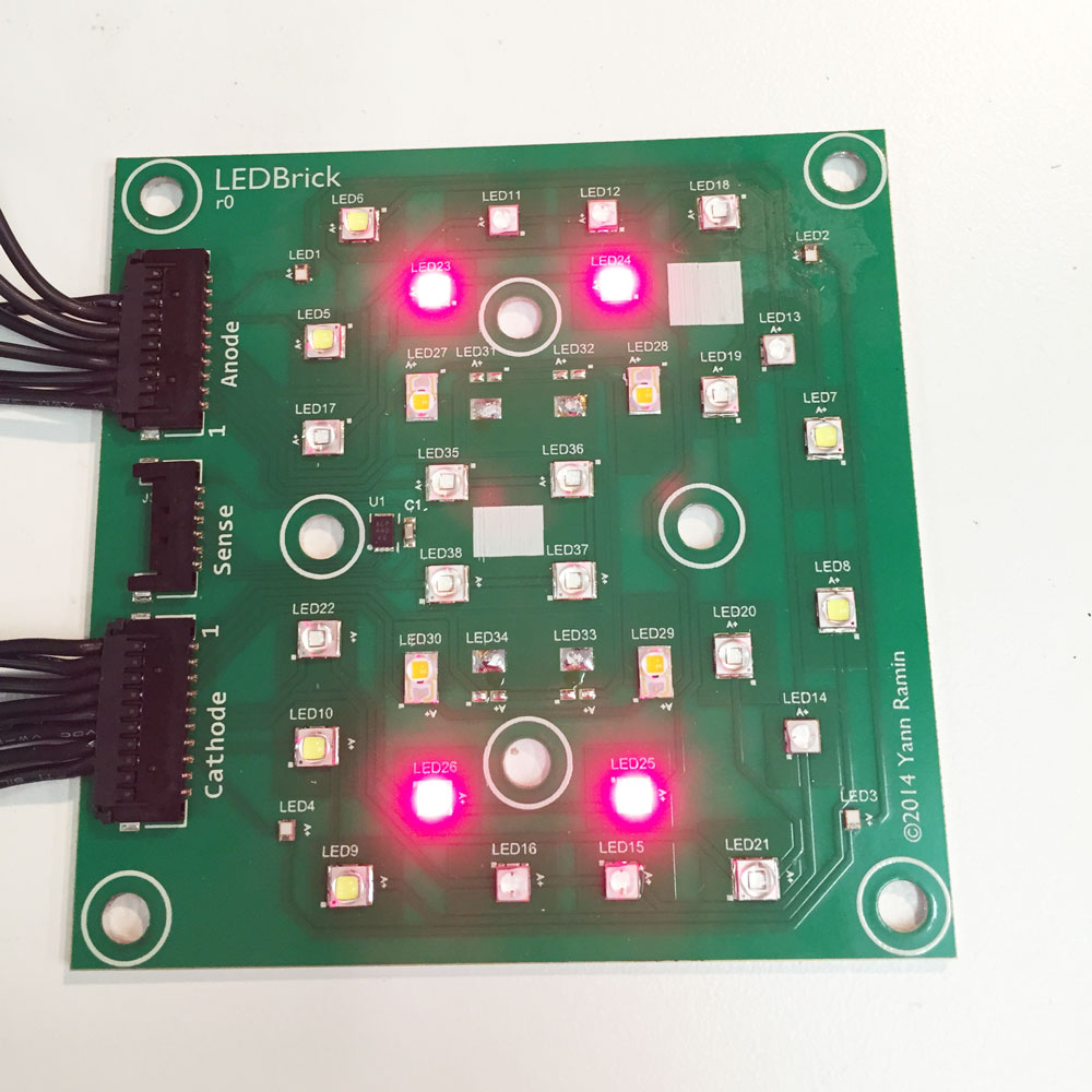
Here you can see three of the four Phillips UV channels operating with the first cable crimp. The bad UV channel was the only defective reflow on the board.
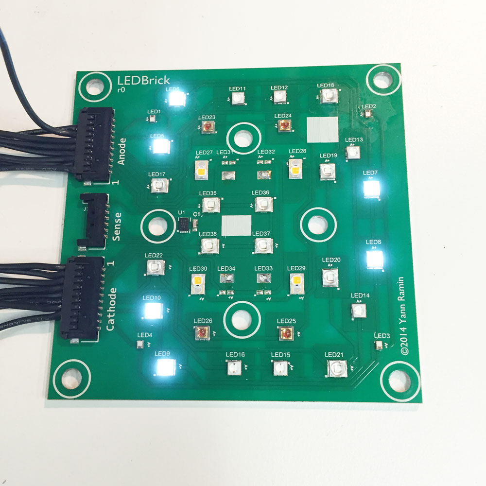
And the white (XP-G2 Cool White):
Royal Blue (Oslon Square):
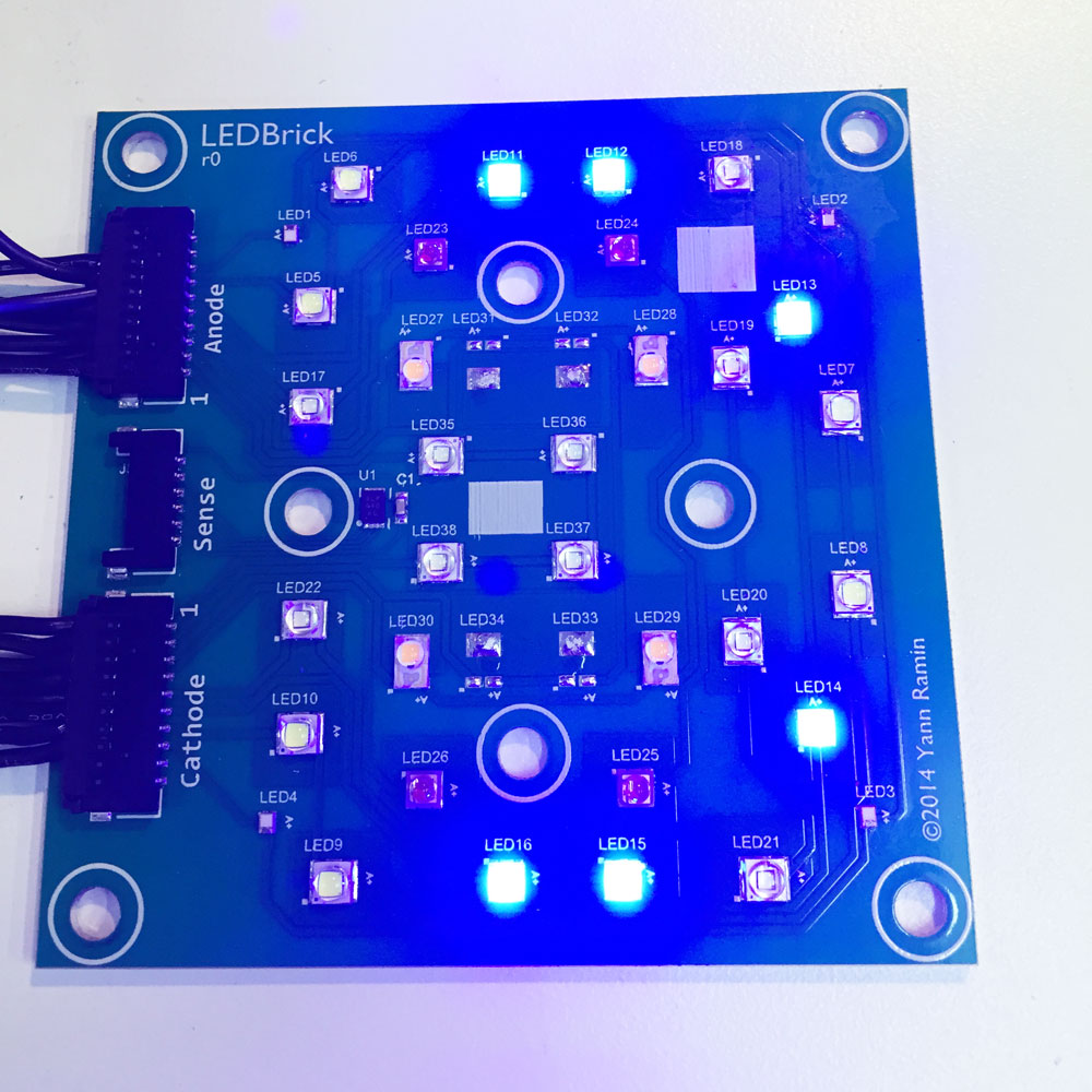
Blue (XP-E Blue):
Red (Osram SSL Hyper Red)
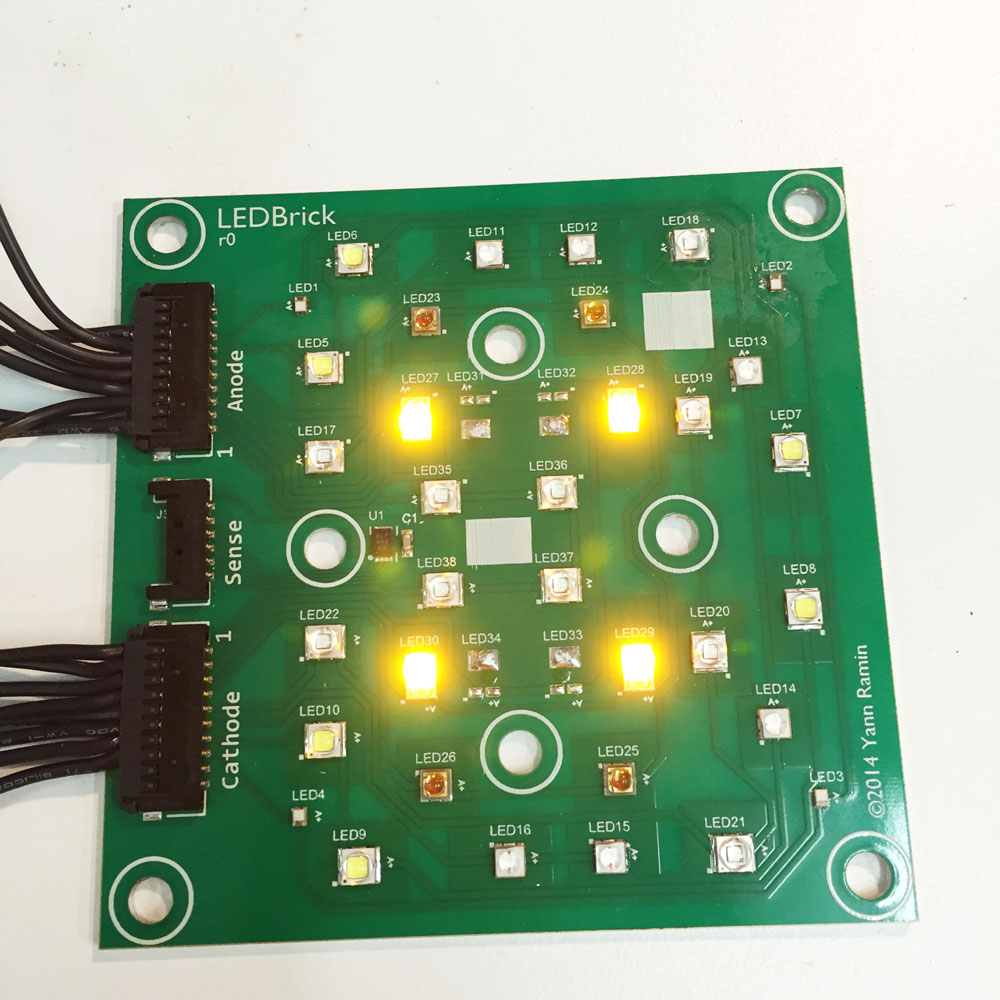
PC Amber (Rebel PC Amber)
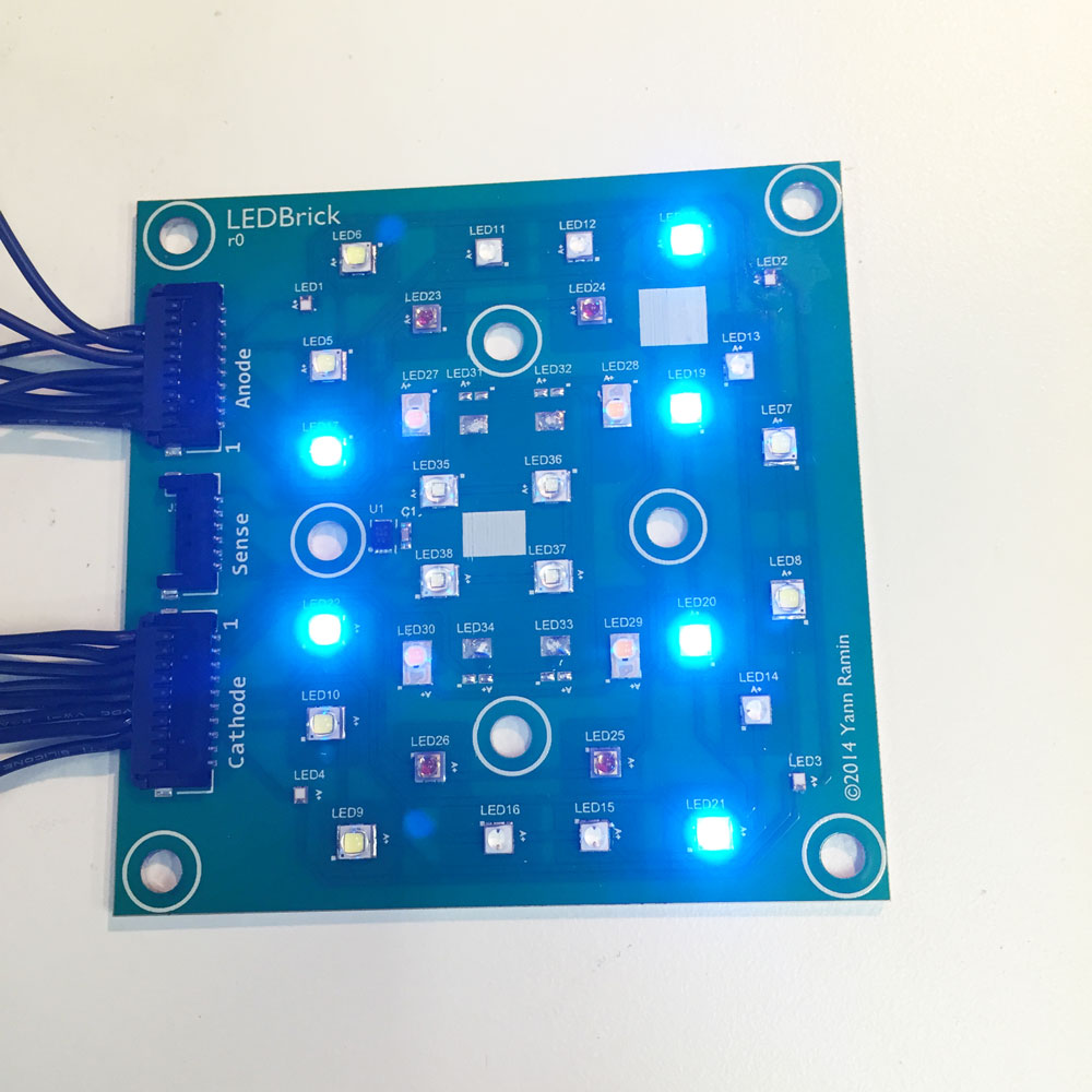
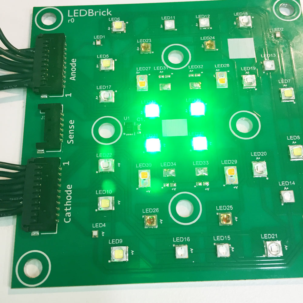
Green (XP-E)
More tesing at load
Running some thermal and output tests using three channels running at design-maximum output (750mA). I’m also monitoring PAR output using a Apogee PAR sensor (multiple: x5). There is no thermal paste or other gap-filler material between the PCB and the heatsink, as a baseline measurement.
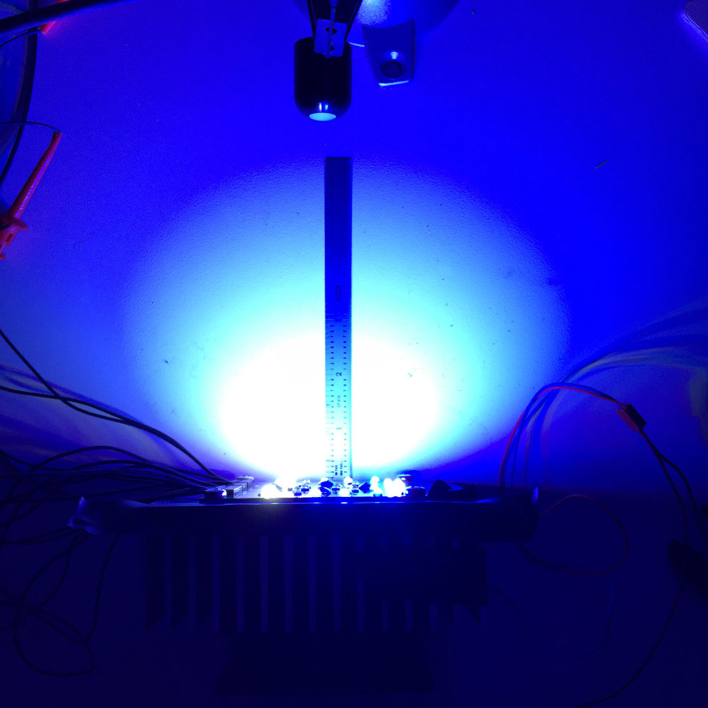
PAR sensor, at 6 inches, centered. Don’t consider this absolute, its mainly to check for thermal-related output reduction.
Output levels, holding steady for 30 minutes so far:
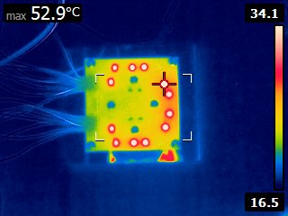
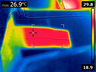
Thermal testing
No fan, two channels running. The top-right royal blue has the highest measurable temperature from the (hacked to 320x240) FLIR-E4. This is a close approximate of die temperature - IR is going to be limited by the silicone lens of course.
Note that shiny aluminum heatsinks are not directly measurable using IR - in later images I’ve placed pieces of black electrical tape over sections of the heatsink to provide a better radiator. Ambient is approximately 18C in all of these images.
Three channels operating - sorry about the funny angle, I had already setup the PAR test at this point. Low-CFM Panaflo is running at 9V (basically inaudible)
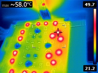
Side of the heatsink with electrical tape to get a temperature read.
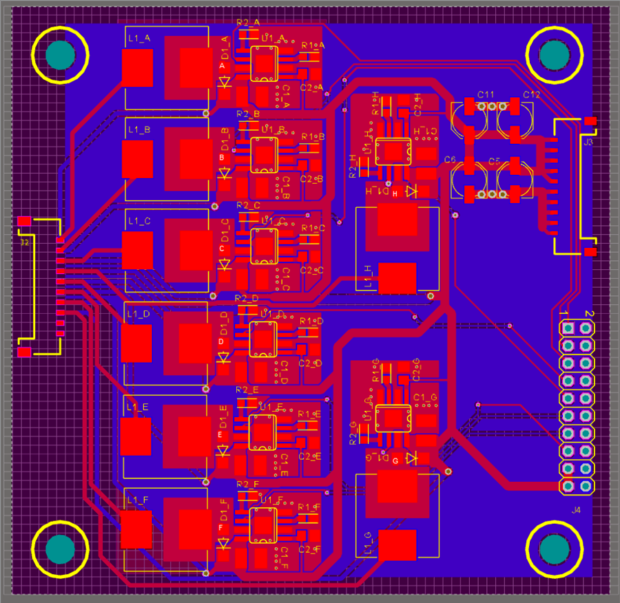
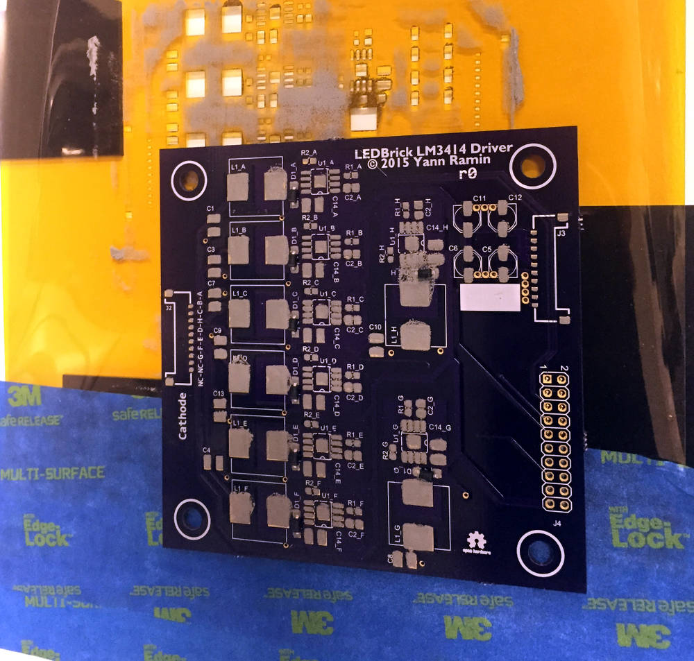
Driver Design
The driver board is based on the TI LM3414 which offers both a sense-resistor-less design, 1A peak current integrated switch, and full PWM control. The current is set as a voltage drop across a set pin, and can be fed externally using other sources (programmable max current anyone) - in this design, it uses a fixed resistor, set to a nominal 500mA output.
The initial driver layout:
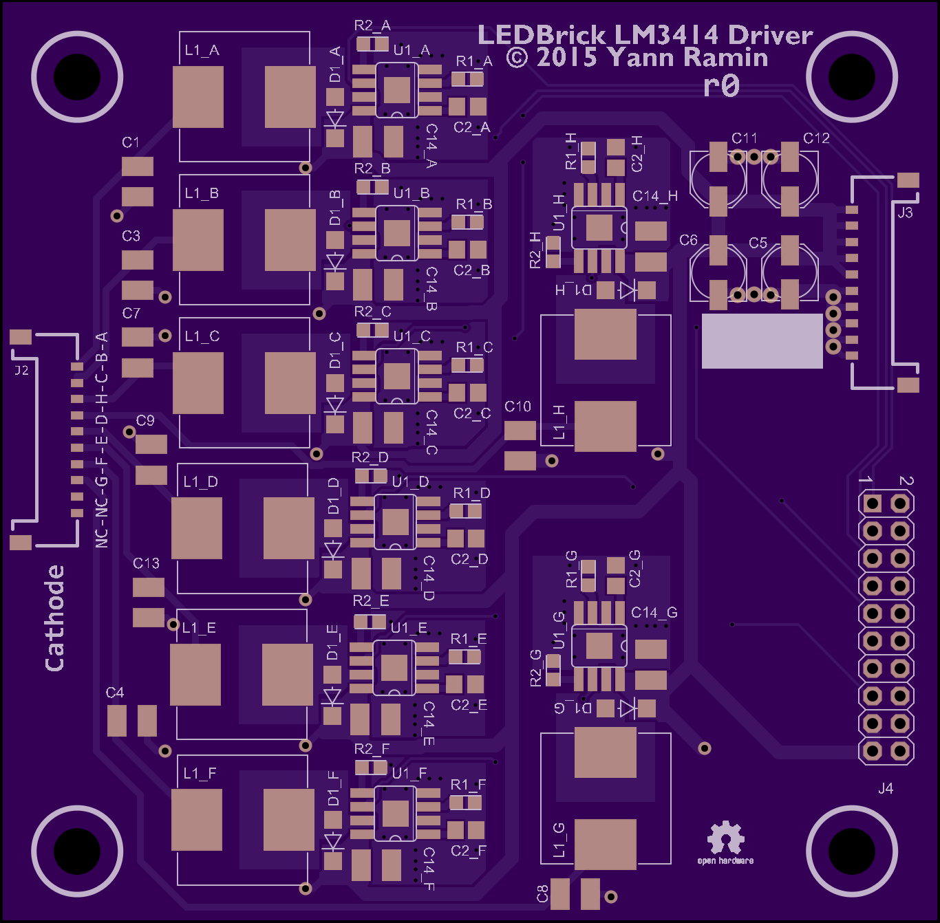
What OSHPark thinks it looks like:
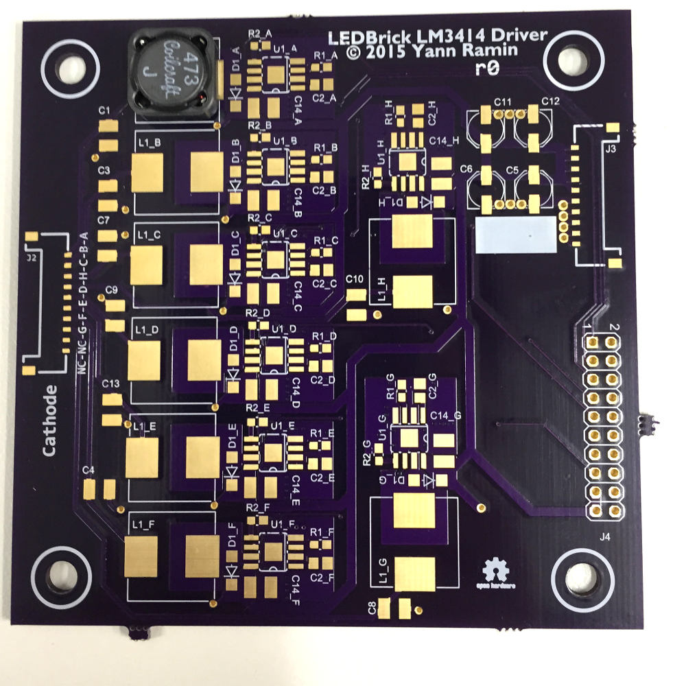
And a fit-test of components from the first board received:
Building the driver
A similar stencil and hot plate method is employed here, since the design is highly repetitive and this speeds up component placement by hand (as opposed to hand-tacking and soldering all the parts):
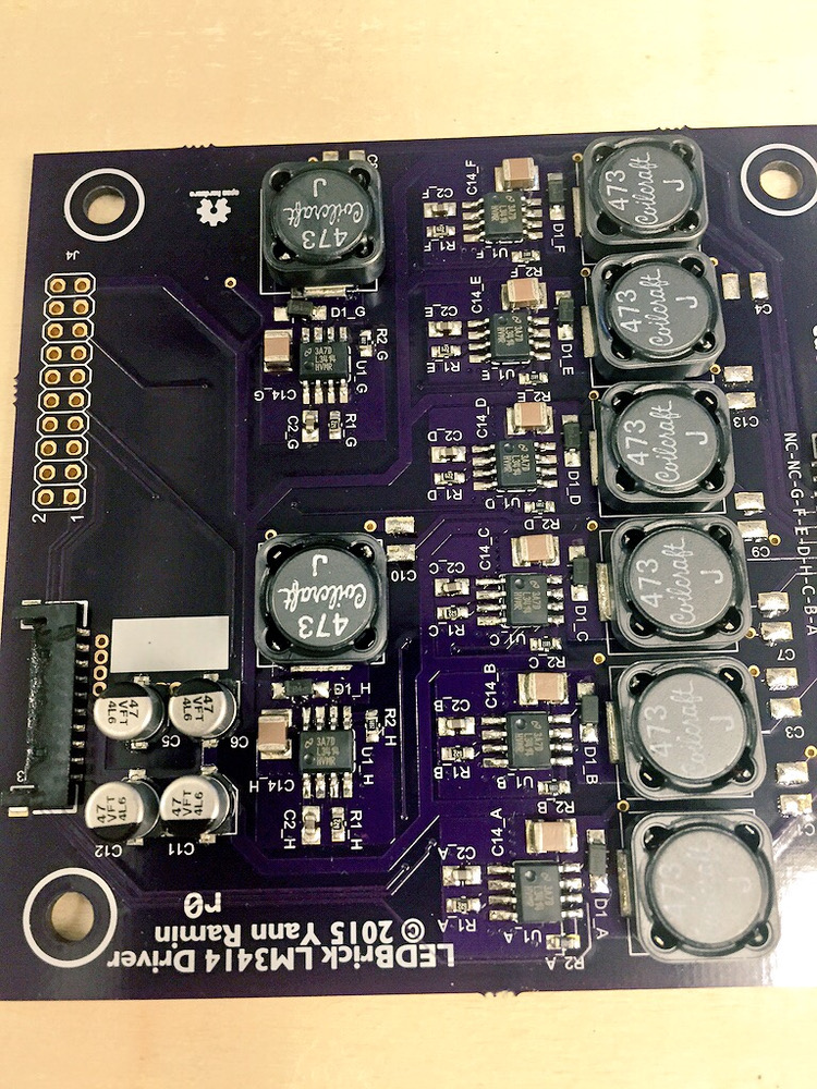
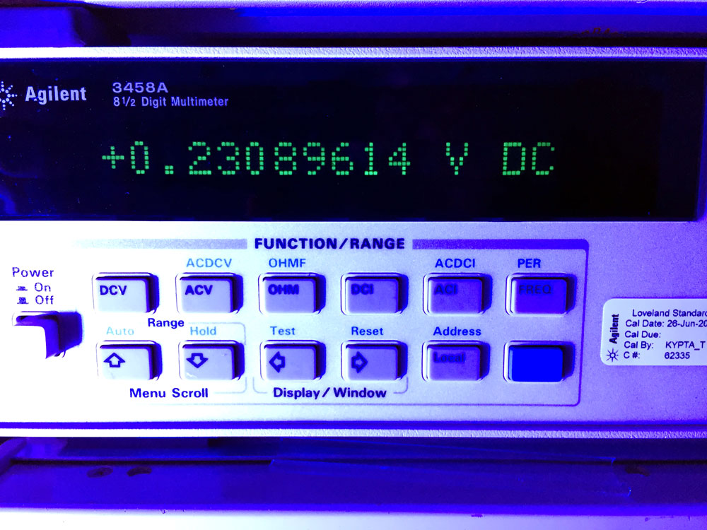
And a basic test of the driver board to see if it works as advertised:
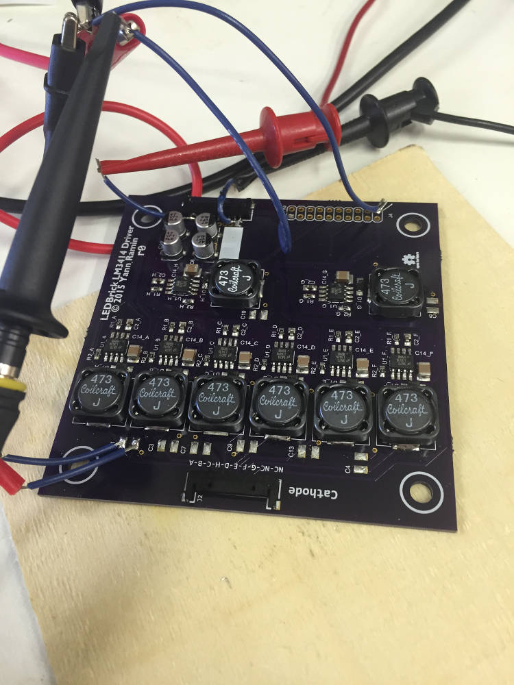
The OSH Park project is available for ordering.
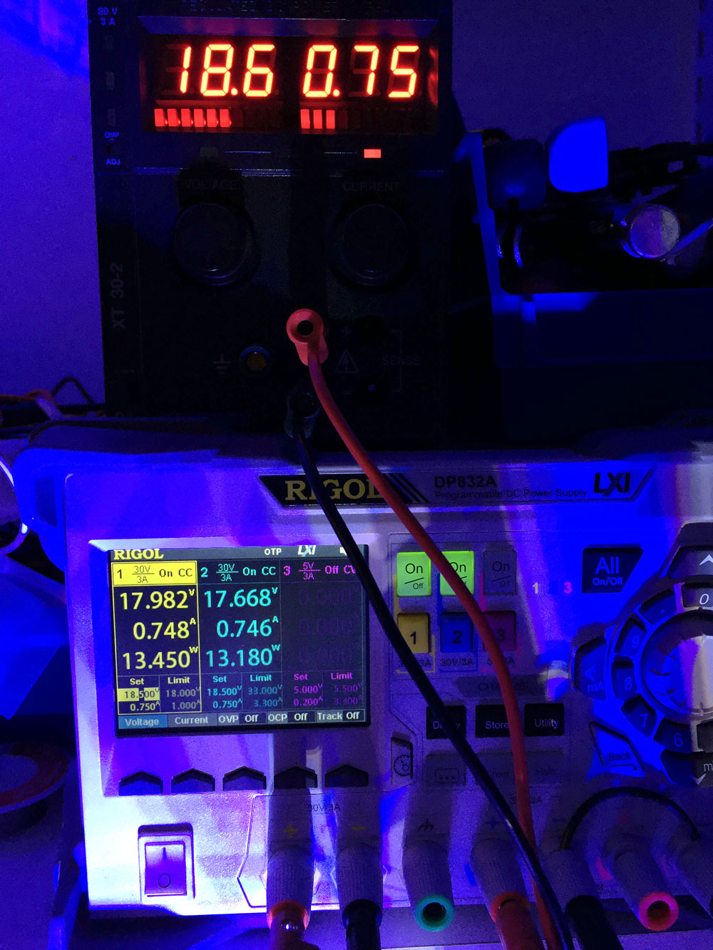
Driver testing, all connected
And the final test, the driver board fully connected:
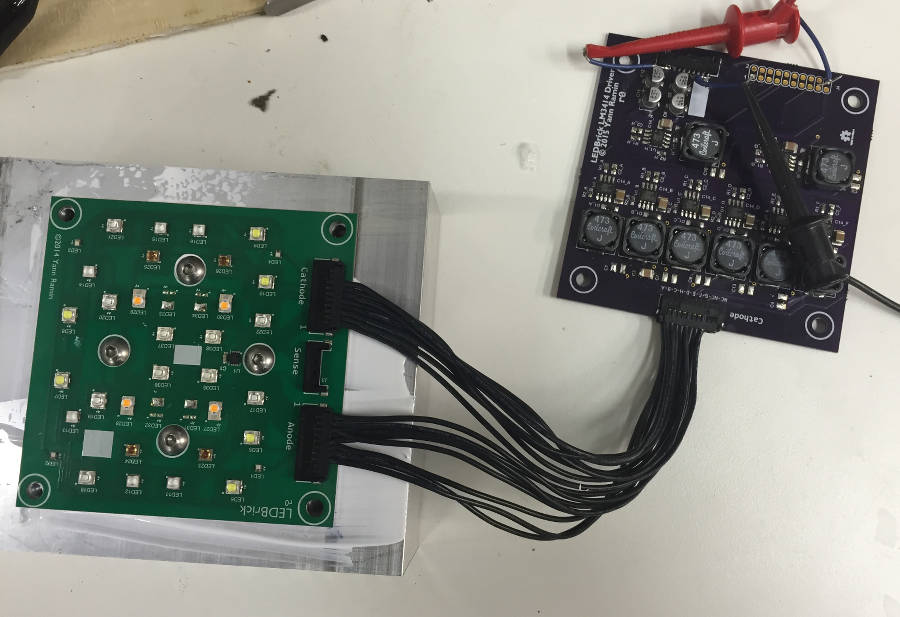
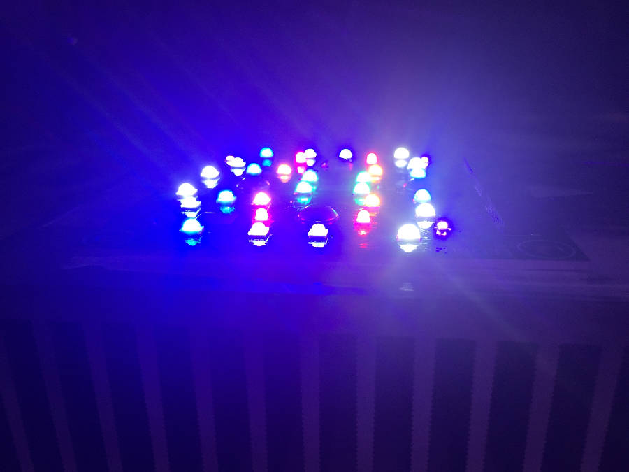
And with all channels operating:
Whats next
There is still a major omission in the design: the PWM controller board. More on that next!