This design has been on my back-burner for quite awhile, but its time to write it up and continue pressing on.
I really like reef aquariums. I currently have a (modest) 90 gallon system, which has livestock dating back to when I started keeping salt-water systems in college (circa 2004). How I managed to actually afford keeping a salt-water system in college is beyond me, but things have progressed nicely.
Background
In keeping corals and photosynthetic clams, lighting is a big deal. Packing hundreds of watts of metal-halide and fluorescent lights above several square feet of space is not at all uncommon, but is also hot and noisy (fans). My current tank is lit by 6 high-output (54W) T5 fluorescent lamps (all bulbs made by ATI). They are driven by a pair of IceCap ballasts, which will over-drive each bulb to an output level of around 80W. Its a very high light environment, and honestly doesn’t do much to promote deep coloration in corals (some fault in over-driving the bulbs when not essential). It also runs fairly hot, and the ballasts have a pretty terrible power factor, leading to high breaker loading in the main aquarium circuit.
The current technology in lighting, and including aquarium lighting, is LEDs. While conventional LED lights are fantastic for interior lighting, they are not full spectrum lights required for under-water photosynthesis. Deeper water organisms will generally respond best to higher energy light, such as greens, blues, and violet/UV (water will filter out low-energy light, such as reds, very early in depth). A common “white” LED has a pronounced blue peak (the underlying emitter) and a yellow/green peak. However, the blue peak is relatively narrow, and often at 450nm, while a more balanced spectrum including frequencies down to 410nm and up to 500nm are generally regarded as ideal.
Commercial fixtures such as the EcoTech Radion form a more full-spectrum lighting arrangement by including a series single-spectrum (non-phosphor) LEDs. Each channel is also individually controllable in order to balance the spectrum both in output, and in aesthetics to the human (and feline) tank watchers.
The LED Brick Concept
While I can easily plunk down the cash to buy a real engineered fixture, and it would probably save me money, thats “not fun.”
There are three major components in an LED lighting setup:
- The mounting board for the actual LED emitters, arranged into channels which are LEDs wired in series.
- A set of constant current drivers for each LED channel
- A controller for the drivers, adjusting output via PWM (Pulse Width Modulation) along with time-keeping functionality.
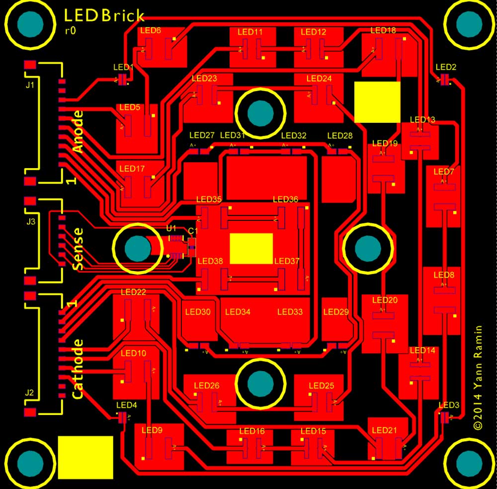
My intent is to produce a monolithic “puck” LED emitter board containing a series of dies arranged into channels on one metal-core single layer PCB. The metal core is essential for heat conduction from the dies to an underlying heat sink - normal fiberglass is not capable of moving enough heat easily from the LEDs, which have a life span dictated by how hot they get.
The board is designed to fit in the footprint of an 80mm fan, which will be arranged via threaded rods through the heatsink to the brick. The drivers and controller will then be stacked above the fan, forming a wide pendant.
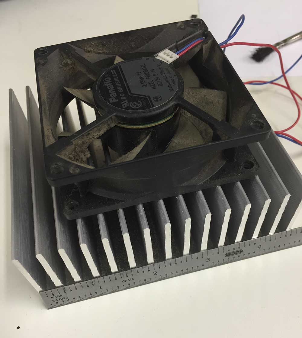
The above image shows the heatsink stock cut to size, along with a very dirty old fan as reference of the desired shape. Any heatsink could be used here - this is a bit oversized for good measure.
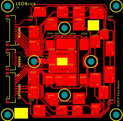
The LED emitter board (LEDBrick)
The design packs a large number of LEDs on the emitter board, more than the normal suggested level for aquarium LED lighting (and more than the competition).
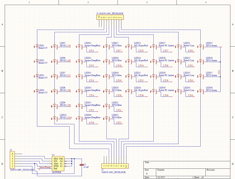
The pads and suggested LEDs are:
- 4 Rebel UV emitters (these are very expensive, but more efficient than the popular Chinese SemiLEDs emitters. They however do not have a primary optic - more on this later)
- 6 Cree XP-G(2) White emitters (or any Cree XP package)
- 6 Cree XP-E Blue emitters (or any Cree XP package)
- 6 Osram Oslon Squre Deep Blue emitters
- 4 Osram SSL Hyper-Red
- 4 Phillips Rebel PC-Amber
- 4 Phillips Rebel Cyan
- 4 Cree XP-E Green
for a total of 38 emitters on the PCB. Emitters can be skipped by simply jumpering over the pads.
The reason for the emitter count is to produce equivalent light levels of commercial units, but at lower current levels - there is no need to drive these units at anywhere near the peak (1.5A, 700ma) currents. There is an efficiency gain (from data-sheet numbers) to be had, at a loss of cost efficiency (even in the long run).
A downside to the large emitter count is the inability to provide secondary-optics, focusing the light tighter than 120 degrees from the primary optic. The emitters are simply too close together to use commercially available lenses, which feature large footprints. I intend to run these pendents very close to the water, which would not need or even suggest the use of an optic.
Also integral to the board is a Microchip MCP9808 I2C temperature sensor. The sensors ground pad is brought out to one of the mounting screws, in an effort to get a good thermal path.
All connectors to the board are a series of Molex PicoLock blade-style high current very flat connectors. I’ve successfully crimped the contacts, however annoying it may be, with the Engineer PA-09 which qualifies it for hobby use (as the Molex official crimping tool is $500). I’ve used the 10-pin and 6-pin connectors, as those are the only ones available in stock at any distributor (a downside to more unique connectors).
Whats next
Keep on following along for more!
I have ordered samples of the LED board, and stencils and parts, for initial validation. Under design is the driver board, using the low cost NCP3066 driver, which has several compromises which I will explain in a new blog post.
(This post was cross-posted to ReefCentral)